…boards do stuff.
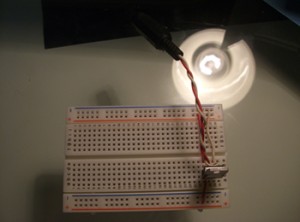
So I’ve finished the first physcomp set of labs. I was going to come into ITP to do it but somehow I ended up waking up and doing it all at home. It went quicker/easier than I thought it would. Here’s a snapshot of Lab 1. I happened to have some spare wire in a toolbox as well as an old soldering iron I pillaged from my father a few days ago. Used white wires instead of black for the ground but *Oh well*.

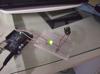
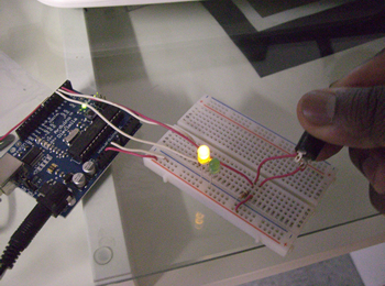
Next was Lab 2. The wiring was a piece of cake but the program gave me a good 1/2 hour of trouble. I downloaded it, unzipped it, installed the drivers and… the bloody program wouldn’t run. I read the help file, ran the .bat file, cried, begged, pleaded, googled… and finally found out why. It seems that there’s a bug related to your set background color in Windows. Read about it here at the Arduino forums. Anyhoo, that resolved it, all worked out. Here’s more pics.


Tuesday night update:
In a lovely case of “let’s-not-and-say-we-did”, here’s the ‘get creative’ part of Lab 2. My MasterPlan(tm) was to make a sort of combination lock. Say you have 3 buttons, you could only turn on the yellow light if you pressed the switches in a certain combination. But… I couldn’t figure out how to do that in Arduino, the problem being that Arduino reads from the i/o ports in a loop instead of recieving trigger signals. So you can see if something is pressed or not but not in what order it was done so (assuming that the switches are set up in parallel like I want). *Ah well.*
New MasterPlan(tm). Set up a domino-like series of books having each book land on a switch. When all 3 switches are pressed, BOOM, it all lights up.
LATE Tuesday Night
Had a flash of insight while on the thinking seat (where the best ideas occur). Thought I’d put this problem aside but guess not. I figured out a way to make the Original MasterPlan(tm) work. So if you have a couple ints set up as flags, you can see what’s currently pressed and what isnt and use that to see that the buttons are pressed in order. The arduino code would look as follows. (The circuit would be similiar to the one in lab two but with one less LED and 2 more switchies.)
int switchPin1 = 2;	//  digital input pin for a switch
int switchPin2 = 3;
int switchPin3 = 4;

int ledPin = 3;		//  digital output pin for an LED

int switchState1 = 0;   // the state of a switch
int switchState2 = 0;
int switchState3 = 0;

int goTime = 0;		// when this hits 3, the led will shine

void setup() {
  pinMode(switchPin1, INPUT);       // set switch pin to be an input
  pinMode(switchPin2, INPUT);
  pinMode(switchPin3, INPUT);

  pinMode(ledPin, OUTPUT);	   // set the LED pin to be an output
}

void loop() {

  switchState1 = digitalRead(switchPin1);	// read switch input
  switchState2 = digitalRead(switchPin2);
  switchState3 = digitalRead(switchPin3);

  /* basically, make sure only one button is pressed at any time */
  if (  ((switchState1 == 1) && (switchState2 == 1)) ||
	((switchState1 == 1) && (switchState3 == 1)) ||
	((switchState2 == 1) && (switchState3 == 1))     ) {

	goTime = 0;
  }
  else {
  /*
     Now we see which order the buttons are pressed in.
     A failure in the combination will reset the whole thing.
     Oh yea, the combination will be... 2, 3, 1.
     Longer combinations are possible though. e.g. 2,3,2,1,3
     just, the math would be different.
  */
    if (switchState1 == 1) { if(goTime != 2) { goTime=0; } else {goTime++;} }
    if (switchState2 == 1) { if(goTime != 0) { goTime=0; } else {goTime++;} }
    if (switchState3 == 1) { if(goTime != 1) { goTime=0; } else {goTime++;} }

  }

  /* This little light of mine... I'm gonna let it shine... */
  if(goTime == 3) { digitalWrite(ledPin, High); }
}
Ninja update
Hm… didn’t think about putting a delay in the code to account for the constant-read. Just saw Zoe’s in class and her combo lock works beatifully.
